
We solve this problem by mounting Smart Tags near hand valves. A Tag is scanned by an ATEX Device, after which the corresponding valve status automatically becomes visible in the control room.

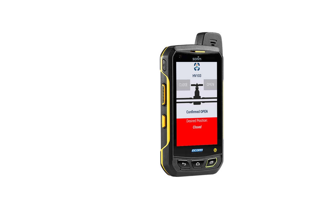
| The communication between the ATEX device in the field and the software in the control room is done via a (very) secure and dedicated connection. | It’s also possible to pass a desired valve position or a list of desired valve positions (e.g. initiated from the control room) to the ATEX Device. So, after scanning an NFC Tag the actual valve position can be compared to the desired valve position and appropriate action can be taken. |
Some example interfaces
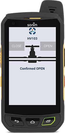
Icon Button Interface
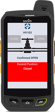
Icon Button Interface with Correct Position Indication
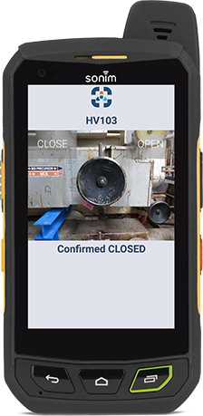
Photo Button Inteface
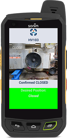
Photo Button Interface with Correct Position Indication
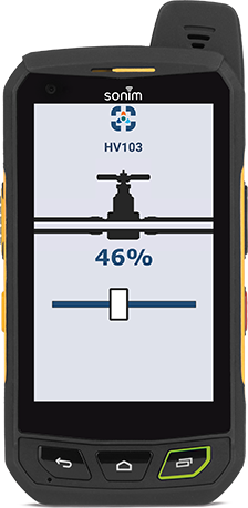
Icon Slider Interface
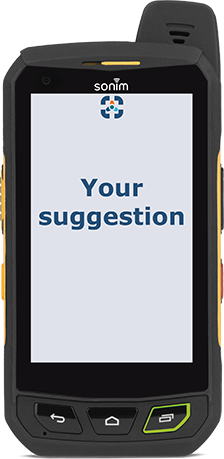
Imagine yours and we will implement it
|
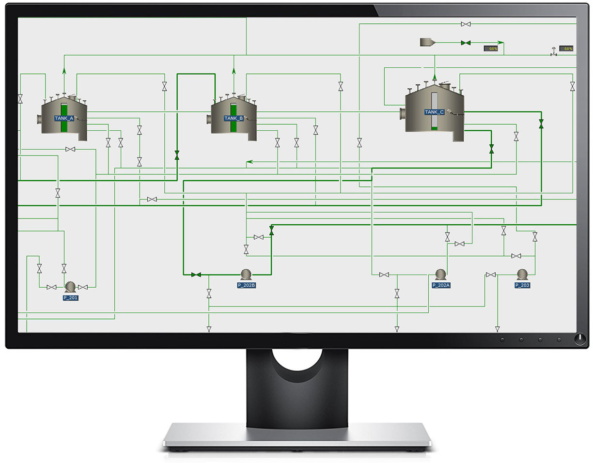
The control room has a dynamic overview showing the current valve positions. There are several possibilities for the visualization of the valve positions. Below is an example of a tank terminal, in which the open valves are colored green. The lines in which these open valves are located have a thicker line-weight to indicate that flow is possible. The closed valves in this example are white and the lines are thin.
Typically, the P&ID’s are used for the dynamic valve position overviews, but optionally also the DCS screens can be adapted (and connected to the valve position software) to show the valve positions of important valves (and/or to pass desired valve positions to the ATEX Device). In our dynamic valve position overview software you can intuitively browse through all the relevant P&ID’s. Also, the Valve Identifiers (e.g. the P&ID Tag names) can be easily shown or hidden in the overviews. For each valve, a history list is available when it has been scanned and what the position was at that time. |
|